
History of Mapping and Surveying:
• First Maps were mental maps. Early hunters and gatherers used mental maps to navigate overland.
• About 5000 years ago the Babylonians produced property descriptions and simple property maps on stone tablets.
• First known surveying by ancient Egyptians- used to reestablish property corners destroyed by flooding of R. Nile.
• About 2000-2500 years ago Greeks and Romans surveyed and mapped their new settlements with a great degree of precision using methods that changed very little up to this century.
Instruments: Chain, Tape, Theodolites, Compass, Levels, TS Classical Methods Triangulation/trilateration: 19th 20th Cen..

Brief History of Navigation:
• PreHistory - Present: Celestial Navigation
• Ok for latitude, poor for longitude until accurate clock invented ~1760
• 13th Century: Magnetic Compass
• 1907: Gyrocompass
• 1912: Radio Direction Finding
• 1930’s: Radar and Inertial Nav
• 1940’s: Loran-A
• 1960’s: Omega and Transit
• 1970’s: Loran-C
• 1980’s: GPS
 |
| Figure 1: Navigation accuracy comparison |
Early Space-Based Radio Navigation System:
• Launch of Sputnik – Tracking? -------------Doppler Shift. Altitude: 985km; revolution period: 98 min
• Frank McClure, of the Applied Physics Laboratory, made a suggestion: would it be possible to invert this problem? – given rise to TRANSIT in late 1950’s (US- 6 sat; Altitude: 1100km; revolution period: 108 min) / TSYKLON(USSR-10 sat; 6- PARUS: Military; 4- TSIKADA-commercial/civilian; Altitude: 1000km)
• The Navy Navigational Satellite System or TRANSIT, used observed measurements in Doppler shift to calculate distance and position to satellites (till 31-12-96).
• A fix requires 40 minutes for a static user-2D.
Space- Vs. Ground-based Nav. Systems:
• High frequency (short wave-length) radio signals, necessary for optimal atmospheric penetration, require line-of-sight transmission paths.
• Ground-based systems are limited to objects above ground.
• Space-based systems see much more of the Earth’s surface.
NAVSTAR Global Positioning System:
• In 1973 the U.S. DOD decided to establish, develop, test, acquire, and deploy a spaceborne Global Positioning System (GPS), resulting in the NAVSTARGPS (NAVigation Satellite Timing And Ranging Global Positioning System).
• “It is an all-weather, space based navigation system development by the U.S. DOD to satisfy the requirements for the military forces to accurately determine their position, velocity, and time in a common reference system, anywhere on or near the Earth on a continuous basis”.
GPS General Characteristics:
• Developed by the US DOD
• Provides
• Accurate Navigation
• 10 - 20 m
• Worldwide Coverage
• 24 hour access
• Common Coordinate System
• Designed to replace existing navigation systems
• Accessible by Civil and Military
• The first GPS satellite PRN 4 was launched on February 22, 1978.

Space Segment:
(Initial Operational Capability(IOC)-1993)
(Full Operational Capability(FOC)-1995)
BLOCK I Satellite:
Rockwell Internationa was awarded a contract in 1974 to build the first eight Block I satellites. In 1978, the contract was extended to build an additional three Block I satellites. Beginning with Navstar 1 in 1978, ten "Block I" GPS satellites were successfully launched. One satellite, "Navstar 7", was lost due to an unsuccessful launch on 18 December 1981.
Block II/IIA:
First Launch: 14 Apr 89(89-97) Total II Series: 27 (1+14+12+8)
 |
| Block II/IIA |
Block IIR / IIR-M(L2C & code M on both L1& L2):
First Launch: 22 Jul 1997/25Sep2005 Total=12/8 (R: Replenishment; M: Modernized)
 |
| Block IIR / IIR-M |
Block IIF:
First Launch: 2009 Acquiring up to 19 SV’s
 |
| Block IIF |
GPS System Components:
• Development costs estimate ~$12 billion
• Annual operating cost ~$400 million
• 3 Segments:
• Space: Satellites
• User: Receivers
• Control: Monitor & Control stations
• Prime Space Segment contractor: Rockwell International/Boeing than Lockheed Martin and again Boeing.
• Coordinate Reference: WGS-84
• Operated by US Air Force Space Command (AFSC)
• Mission control center operations at Schriever (formerly Falcon) AFB, Colorado Springs.
 |
| GPS System Component |
Space Segment:
• 24 Satellites
• 4 satellites in 6 Orbital Planes inclined at 55 Degrees
• 20200 Km above the Earth
• Every satellite is visible from minimum 2 ground stations
• 12 Hourly orbits – In view for 4-5 hours
• Designed to last 7.5 years
• Different Classifications – Block 1, 2, 2A, 2R & 2 F

Control Segment:
• Master Control Station
• Responsible for collecting tracking data from the monitoring stations and calculating satellite orbits and clock parameters
• 5 Monitoring Stations
• Responsible for measuring pseudorange data. This orbital tracking network is used to determine the broadcast ephemeris and satellite clock modeling
• Ground Control Stations with Antenna (S-band, uplink), Responsible for upload of information to SV’s
• Routine maintenance

User Segment- Who uses it:
• The most visible segment - Everyone!
• GPS receivers are found in many locations and applications
• Merchant, Navy, Coast Guard vessels
• Surveyors
• Has completely revolutionized surveying
• Hikers, Mountain Climbers, Backpackers
• Cars now being equipped
• Communications & Imaging Satellites
• Space-to-Space Navigation
• Any system requiring accurate timing
• Commercial Truckers, Commercial Airliners, Civil Pilots

Why use GPS:
• Weather Independent(Rain/fog/snow have no effect on signals)
• Does not require line of sight
• Gives high Geodetic Accuracy
• Can be operated day and night
• Quicker and requires less manpower
• Economical advantages
• Common Coordinate System
• Wide Range of Applications
• Competitively Priced
How It Works:
• GPS is a ranging system (triangulation)
• The “reference stations” are satellites moving at 4 km/s
1. A GPS receiver (“the user”) detects 1-way ranging signals from several satellites
• Each transmission is time-tagged
• Each transmission/ephemeris contains the satellite’s position
2. The time-of-arrival is compared to time-of-transmission
3. The delta-T is multiplied by the speed of light to obtain the range
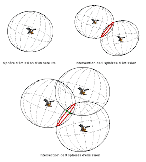
4. Each range puts the user on a sphere about the satellite
5. Intersecting several of these yields a user position
Outline Principle : Range
Range = Time Taken x Speed of Light
A receiver in autonomous mode provides navigation and positioning accuracy of about 10 to 100 m due to the effects of GPS errors.
Multi-Satellite Ranging:
1. 1 range puts user on the spherical face of the cone.
2. Intersecting with a 2nd range restricts user to the circular arcs.
3. A 3rd range constrains user to 1 of the 2 points.
 |
Outline Principle:
Position:
• The satellites are like “Orbiting Control Stations”
• Ranges (distances) are measured to each satellite using time dependent codes
• Typically GPS receivers use inexpensive clocks. They are much less accurate than the clocks on board the satellites
• A radio wave travels at the speed of light
• (Distance = Velocity x Time)
• Consider an error in the receiver clock
• 1/10 second error = 30,000 Km error
• 1/1,000,000 second error = 300 m error
Timing:
• Accuracy of position is only as good as your clock
• To know where you are, you must know when you receive.
• Receiver clock must match SV clock to compute delta-T
• SVs carry atomic oscillators (2 rubidium, 2 cesium each)
• Not practical for hand-held receiver
• Accumulated drift of receiver clock is called clock bias
• The erroneously measured range is called a pseudorange
• To eliminate the bias, a 4th SV is tracked
• 4 equations, 4 unknowns
• Solution now generates X,Y,Z and b
• If Doppler also tracked, Velocity can be computed
GPS Time:
• GPS time is referenced to 6 January 1980, 00:00:00
• Jan 6 = First Sunday in 1980
• GPS satellite clocks are essentially synched to International Atomic Time (TAI) (and therefore to UTC/zulu time since Jan. 1, 1972 for global civil time)
• TAI, maintained at Lab., France, is the basis for Coordinated Universal Time (UTC), used for most civil timekeeping
• GPS time = TAI + 13s
• Since 13 leap seconds existed on 1/6/1980
• GPS time drifts ahead of UTC as the latter is “held” (leap seconds) to accommodate earth’s slowing
• Delta between GPS SV time & UTC is included in nav/timing message
• SV clocks good to about 1 part in 1013
• Effectively, GPS time starts with zero at the beginning of each week.
GPS Signal Structure:
• Each GPS satellite transmits a number of signals
• The signal comprises two UHF carrier waves (L1-19cm and L2-23cm) and two codes as low power radio signals (C/A on L1 and P or Y on both L1 and L2) as well as a satellite orbit message.
• Bandwidth allocated for L1-24 MHz, L2-22 MHz, & L5-28 MHz
Precise (P) Code:
• Generally encrypted into the Y-code (A.S.)
• Requires special chip to decode
• Modulates both L1 & L2
• Also modulated by Nav/Time data message
• Chipping rate=10.23 MHz (λ=29.30m) i.e. 10 times faster than C/A code ensuring improved time measurement.
• Sequence Length = 2.35*1014 bits, thus Period = 266 days
• P-code rate is the fundamental frequency (provides the basis for all others)
• P-Code (10.23 MHz) /10 = 1.023 MHz (C/A code)
• P-Code (10.23 MHz) X 154 = 1575.42 MHz (L1).
• P-Code (10.23 MHz) X 120 = 1227.60 MHz (L2).
Coarse Acquisition (C/A) Code:
• 1023-bit Gold Code
• Originally intended as simply an acquisition code for Pcode receivers
• Modulates the L1 only
• Chipping rate = 1.023 MHz (λ=290 meter)
• Sequence Length = 1023 bits, thus Period = 1 millisec
• Provides the data for Standard Positioning Service (SPS)
• The usual position generated for most civilian receivers
• Modulated by the Navigation/Timing Message code
The Almanac:
• In addition to its own nav data, each SV also broadcasts info about ALL the other SV’s
• In a reduced-accuracy format
• Known as the Almanac
• Permits receiver to predict, from a cold start, “where to look” for SV’s when powered up
• GPS orbits are so predictable, an almanac may be valid for months
• Almanac data is large
• 12.5 minutes to transfer in entirety
Range Determination from Code Observations:
• Pseudoranges (Code)
• PRN uniquely identifies each satellite.
• PRN provides timing coordination for GPS.
• PRN enable amplification of signals.
• Each satellite sends a unique signal which repeats itself approx. 1 msec.
• Receiver compares self generated signal with received signal (correlation process) for synchronization of Receiver clock with the satellite clock.
• From the time difference (dT) a range observation can be determined.

Range Determination from Phase Observations:
• Phase Observations
• Wavelength of the signal is 19 cm on L1 and 24 cm on L2
• Receiver compares self-generated phase with received phase
• Number of wavelengths is not known at the time the receiver is switched on (carrier phase ambiguity)
• As long as you track the satellite, the change in distance can be observed (the carrier phase ambiguity remains constant)

Initial Phase Ambiguity:
• Initial phase Ambiguity must be determined to use carrier phase data as distance measurements over time
 |
| Source: WP (Aaron Boda) |
D = c ΔT + λN
GPS Surveying Techniques:
• Static
• For long baselines (>20Km), where the highest possible accuracy is required
• This is the traditional technique for providing Geodetic Networks and the only solution for large areas
• Rapid Static
• For baselines up to 20Km
• Short Occupation times/high production
• Stop and Go
• Detail Surveys. Any application where many points close together have to be surveyed
• Fast, economical & Ideal for open areas
• Kinematic
• Used to track the trajectory of a moving object (continuous measurements)
• Can be used to profile roadways, stockpiles, etc.
Satellite Geometry:
• Satellite geometry can affect the quality of signals and accuracy of receiver trilateration.
• Positional Dilution of Precision (PDOP) reflects each satellite’s position relative to the other satellites being accessed by a receiver.
• PDOP can be used as an indicator of the quality of a receiver’s triangulated position.
• It’s usually up to the GPS receiver to pick satellites which provide the best position trilateration.
Dilution of Precision (DOP):
• Satellite geometry can affect the quality of signals and accuracy of receiver trilateration.
• A description of purely geometrical contribution to the uncertainty in a position fix.
• It is an indicator as to the geometrical strength of the satellites being tracked at the time of measurement
– GDOP (Geometrical)
• Includes Lat, Lon, Height & Time
– PDOP (Positional)
• Includes Lat, Lon & Height
– HDOP (Horizontal)
• Includes Lat & Lon
– VDOP (Vertical)
• Includes Height
 |
| Source: Onsky Blog |
QUALITY DOP
Very Good 1-3
Good 4-5
Fair 6
Suspect >6
Satellite Geometries:
| Ideal Satellite Geometry |
 |
| Good Satellite Geometry |
 |
| Skewed Satellite Geometry |
 |
| Poor Satellite Geometry |
Satellite Mask Angle:
 |
| Elevation and Mask Angle |
Single Frequency Receivers:

Error Budget:
GNSS:
The theoretical definition:
 |
| Source: Mobatime |


No comments:
Post a Comment
If you have any doubt, Please let me know