History of Mapping and Surveying:
• First Maps were mental maps. Early hunters and gatherers used mental maps to navigate overland.
• About 5000 years ago the Babylonians produced property descriptions and simple property maps on stone tablets.
• First known surveying by ancient Egyptians- used to reestablish property corners destroyed by flooding of R. Nile.
• About 2000-2500 years ago Greeks and Romans surveyed and mapped their new settlements with a great degree of precision using methods that changed very little up to this century.
Instruments: Chain, Tape, Theodolites, Compass, Levels, TS Classical Methods Triangulation/trilateration: 19th 20th Cen..
Brief History of Navigation:
• PreHistory - Present: Celestial Navigation
• Ok for latitude, poor for longitude until accurate clock invented ~1760
• 13th Century: Magnetic Compass
• 1907: Gyrocompass
• 1912: Radio Direction Finding
• 1930’s: Radar and Inertial Nav
• 1940’s: Loran-A
• 1960’s: Omega and Transit
• 1970’s: Loran-C
• 1980’s: GPS
 |
| Figure 1: Navigation accuracy comparison |
Early Space-Based Radio Navigation System:
• Launch of Sputnik – Tracking? -------------Doppler Shift. Altitude: 985km; revolution period: 98 min
• Frank McClure, of the Applied Physics Laboratory, made a suggestion: would it be possible to invert this problem? – given rise to TRANSIT in late 1950’s (US- 6 sat; Altitude: 1100km; revolution period: 108 min) / TSYKLON(USSR-10 sat; 6- PARUS: Military; 4- TSIKADA-commercial/civilian; Altitude: 1000km)
• The Navy Navigational Satellite System or TRANSIT, used observed measurements in Doppler shift to calculate distance and position to satellites (till 31-12-96).
• A fix requires 40 minutes for a static user-2D.
Space- Vs. Ground-based Nav. Systems:
• High frequency (short wave-length) radio signals, necessary for optimal atmospheric penetration, require line-of-sight transmission paths.
• Ground-based systems are limited to objects above ground.
• Space-based systems see much more of the Earth’s surface.
NAVSTAR Global Positioning System:
• In 1973 the U.S. DOD decided to establish, develop, test, acquire, and deploy a spaceborne Global Positioning System (GPS), resulting in the NAVSTARGPS (NAVigation Satellite Timing And Ranging Global Positioning System).
• “It is an all-weather, space based navigation system development by the U.S. DOD to satisfy the requirements for the military forces to accurately determine their position, velocity, and time in a common reference system, anywhere on or near the Earth on a continuous basis”.
GPS General Characteristics:
• Developed by the US DOD
• Provides
• Accurate Navigation
• 10 - 20 m
• Worldwide Coverage
• 24 hour access
• Common Coordinate System
• Designed to replace existing navigation systems
• Accessible by Civil and Military
• The first GPS satellite PRN 4 was launched on February 22, 1978.
Space Segment:
(Initial Operational Capability(IOC)-1993)
(Full Operational Capability(FOC)-1995)
BLOCK I Satellite:
Rockwell Internationa was awarded a contract in 1974 to build the first eight Block I satellites. In 1978, the contract was extended to build an additional three Block I satellites. Beginning with Navstar 1 in 1978, ten "Block I" GPS satellites were successfully launched. One satellite, "Navstar 7", was lost due to an unsuccessful launch on 18 December 1981.
Block II/IIA:
First Launch: 14 Apr 89(89-97) Total II Series: 27 (1+14+12+8)
 |
| Block II/IIA |
Block IIR / IIR-M(L2C & code M on both L1& L2):
First Launch: 22 Jul 1997/25Sep2005 Total=12/8 (R: Replenishment; M: Modernized)
 |
| Block IIR / IIR-M |
Block IIF: First Launch: 2009 Acquiring up to 19 SV’s
 |
| Block IIF |
GPS System Components:
• Development costs estimate ~$12 billion
• Annual operating cost ~$400 million
• 3 Segments:
• Space: Satellites
• User: Receivers
• Control: Monitor & Control stations
• Prime Space Segment contractor: Rockwell International/Boeing than Lockheed Martin and again Boeing.
• Coordinate Reference: WGS-84
• Operated by US Air Force Space Command (AFSC)
• Mission control center operations at Schriever (formerly Falcon) AFB, Colorado Springs.
 |
| GPS System Component |
Space Segment:
• 24 Satellites
• 4 satellites in 6 Orbital Planes inclined at 55 Degrees
• 20200 Km above the Earth
• Every satellite is visible from minimum 2 ground stations
• 12 Hourly orbits – In view for 4-5 hours
• Designed to last 7.5 years
• Different Classifications – Block 1, 2, 2A, 2R & 2 F
Control Segment:
• Master Control Station
• Responsible for collecting tracking data from the monitoring stations and calculating satellite orbits and clock parameters
• 5 Monitoring Stations
• Responsible for measuring pseudorange data. This orbital tracking network is used to determine the broadcast ephemeris and satellite clock modeling
• Ground Control Stations with Antenna (S-band, uplink), Responsible for upload of information to SV’s
• Routine maintenance
User Segment- Who uses it:
• The most visible segment - Everyone!
• GPS receivers are found in many locations and applications
• Merchant, Navy, Coast Guard vessels
• Surveyors
• Has completely revolutionized surveying
• Hikers, Mountain Climbers, Backpackers
• Cars now being equipped
• Communications & Imaging Satellites
• Space-to-Space Navigation
• Any system requiring accurate timing
• Commercial Truckers, Commercial Airliners, Civil Pilots
Why use GPS:
• Weather Independent(Rain/fog/snow have no effect on signals)
• Does not require line of sight
• Gives high Geodetic Accuracy
• Can be operated day and night
• Quicker and requires less manpower
• Economical advantages
• Common Coordinate System
• Wide Range of Applications
• Competitively Priced
How It Works:
• GPS is a ranging system (triangulation)
• The “reference stations” are satellites moving at 4 km/s
1. A GPS receiver (“the user”) detects 1-way ranging signals from several satellites
• Each transmission is time-tagged
• Each transmission/ephemeris contains the satellite’s position
2. The time-of-arrival is compared to time-of-transmission
3. The delta-T is multiplied by the speed of light to obtain the range
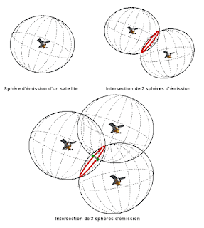
4. Each range puts the user on a sphere about the satellite
5. Intersecting several of these yields a user position
Outline Principle : Range
Range = Time Taken x Speed of Light
A receiver in autonomous mode provides navigation and positioning accuracy of about 10 to 100 m due to the effects of GPS errors.
Multi-Satellite Ranging:
1. 1 range puts user on the spherical face of the cone.
2. Intersecting with a 2nd range restricts user to the circular arcs.
3. A 3rd range constrains user to 1 of the 2 points.
Outline Principle:
Position:
• The satellites are like “Orbiting Control Stations”
• Ranges (distances) are measured to each satellite using time dependent codes
• Typically GPS receivers use inexpensive clocks. They are much less accurate than the clocks on board the satellites
• A radio wave travels at the speed of light
• (Distance = Velocity x Time)
• Consider an error in the receiver clock
• 1/10 second error = 30,000 Km error
• 1/1,000,000 second error = 300 m error
Timing:
• Accuracy of position is only as good as your clock
• To know where you are, you must know when you receive.
• Receiver clock must match SV clock to compute delta-T
• SVs carry atomic oscillators (2 rubidium, 2 cesium each)
• Not practical for hand-held receiver
• Accumulated drift of receiver clock is called clock bias
• The erroneously measured range is called a pseudorange
• To eliminate the bias, a 4th SV is tracked
• 4 equations, 4 unknowns
• Solution now generates X,Y,Z and b
• If Doppler also tracked, Velocity can be computed
GPS Time:
• GPS time is referenced to 6 January 1980, 00:00:00
• Jan 6 = First Sunday in 1980
• GPS satellite clocks are essentially synched to International Atomic Time (TAI) (and therefore to UTC/zulu time since Jan. 1, 1972 for global civil time)
• TAI, maintained at Lab., France, is the basis for Coordinated Universal Time (UTC), used for most civil timekeeping
• GPS time = TAI + 13s
• Since 13 leap seconds existed on 1/6/1980
• GPS time drifts ahead of UTC as the latter is “held” (leap seconds) to accommodate earth’s slowing
• Delta between GPS SV time & UTC is included in nav/timing message
• SV clocks good to about 1 part in 1013
• Effectively, GPS time starts with zero at the beginning of each week.
GPS Signal Structure:
• Each GPS satellite transmits a number of signals
• The signal comprises two UHF carrier waves (L1-19cm and L2-23cm) and two codes as low power radio signals (C/A on L1 and P or Y on both L1 and L2) as well as a satellite orbit message.
• Bandwidth allocated for L1-24 MHz, L2-22 MHz, & L5-28 MHz
Precise (P) Code:
• Generally encrypted into the Y-code (A.S.)
• Requires special chip to decode
• Modulates both L1 & L2
• Also modulated by Nav/Time data message
• Chipping rate=10.23 MHz (λ=29.30m) i.e. 10 times faster than C/A code ensuring improved time measurement.
• Sequence Length = 2.35*1014 bits, thus Period = 266 days
• P-code rate is the fundamental frequency (provides the basis for all others)
• P-Code (10.23 MHz) /10 = 1.023 MHz (C/A code)
• P-Code (10.23 MHz) X 154 = 1575.42 MHz (L1).
• P-Code (10.23 MHz) X 120 = 1227.60 MHz (L2).
Coarse Acquisition (C/A) Code:
• 1023-bit Gold Code
• Originally intended as simply an acquisition code for Pcode receivers
• Modulates the L1 only
• Chipping rate = 1.023 MHz (λ=290 meter)
• Sequence Length = 1023 bits, thus Period = 1 millisec
• Provides the data for Standard Positioning Service (SPS)
• The usual position generated for most civilian receivers
• Modulated by the Navigation/Timing Message code
The Almanac:
• In addition to its own nav data, each SV also broadcasts info about ALL the other SV’s
• In a reduced-accuracy format
• Known as the Almanac
• Permits receiver to predict, from a cold start, “where to look” for SV’s when powered up
• GPS orbits are so predictable, an almanac may be valid for months
• Almanac data is large
• 12.5 minutes to transfer in entirety
Range Determination from Code Observations:
• Pseudoranges (Code)
• PRN uniquely identifies each satellite.
• PRN provides timing coordination for GPS.
• PRN enable amplification of signals.
• Each satellite sends a unique signal which repeats itself approx. 1 msec.
• Receiver compares self generated signal with received signal (correlation process) for synchronization of Receiver clock with the satellite clock.
• From the time difference (dT) a range observation can be determined.
Range Determination from Phase Observations:
• Phase Observations
• Wavelength of the signal is 19 cm on L1 and 24 cm on L2
• Receiver compares self-generated phase with received phase
• Number of wavelengths is not known at the time the receiver is switched on (carrier phase ambiguity)
• As long as you track the satellite, the change in distance can be observed (the carrier phase ambiguity remains constant)
Initial Phase Ambiguity:
• Initial phase Ambiguity must be determined to use carrier phase data as distance measurements over time
 |
| Source: WP (Aaron Boda) |
D = c ΔT + λN
GPS Surveying Techniques:
• Static
• For long baselines (>20Km), where the highest possible accuracy is required
• This is the traditional technique for providing Geodetic Networks and the only solution for large areas
• Rapid Static
• For baselines up to 20Km
• Short Occupation times/high production
• Stop and Go
• Detail Surveys. Any application where many points close together have to be surveyed
• Fast, economical & Ideal for open areas
• Kinematic
• Used to track the trajectory of a moving object (continuous measurements)
• Can be used to profile roadways, stockpiles, etc.
Satellite Geometry:
• Satellite geometry can affect the quality of signals and accuracy of receiver trilateration.
• Positional Dilution of Precision (PDOP) reflects each satellite’s position relative to the other satellites being accessed by a receiver.
• PDOP can be used as an indicator of the quality of a receiver’s triangulated position.
• It’s usually up to the GPS receiver to pick satellites which provide the best position trilateration.
Dilution of Precision (DOP):
• Satellite geometry can affect the quality of signals and accuracy of receiver trilateration.
• A description of purely geometrical contribution to the uncertainty in a position fix.
• It is an indicator as to the geometrical strength of the satellites being tracked at the time of measurement
– GDOP (Geometrical)
• Includes Lat, Lon, Height & Time
– PDOP (Positional)
• Includes Lat, Lon & Height
– HDOP (Horizontal)
• Includes Lat & Lon
– VDOP (Vertical)
• Includes Height
 |
| Source: Onsky Blog |
QUALITY DOP
Very Good 1-3
Good 4-5
Fair 6
Suspect >6
Satellite Geometries:
 |
| Ideal Satellite Geometry |
 |
| Good Satellite Geometry |
 |
| Skewed Satellite Geometry |
 |
| Poor Satellite Geometry |
Satellite Mask Angle:
• Atmospheric Refraction is greater for satellites at angles that are low to the receiver because the signal must pass through more atmosphere.
• There is a trade off between mask angle and atmospheric refraction. Setting high angles will decrease atmospheric refraction, but it will also decrease the possibility of tracking the necessary four satellites.
 |
| Elevation and Mask Angle |
Single Frequency Receivers:
• Baseline Accuracy 1cm/5mm + 2/1ppm (rms)
• Uses Post process L1 carrier phase
• Used for all Surveying tasks with baselines up to 15Km
• Network Densification, Detail Surveys
• Less expensive alternative to Dual frequency
• Most unsophisticated receivers track only L1 and use a simplified correction model
• The “high end” of the GPS Market
• Baseline Accuracy 5/3mm + 1ppm (rms)
• Used in all GPS Surveying tasks :-
• Geodetic Control Networks, Tectonic Plate Monitoring, Network Densification, Phogrammetric Control, Detail Surveys etc.
• New applications are found on a daily basis
Error Budget:
• User Range Errors (URE) consists of System Errors (Ephemeris Data, & Satellite Clocks) and atmospheric Errors (Ionospheric/Tropospheric).
• User Equipment Errors (UEE) consist of Receiver Noise and Multipath error.
• PDOP of 2 means that in the worst case, a 1m URE will result in 2m positional error.
GNSS:
The theoretical definition:
GNSS. A worldwide position and time determination system that includes one or more satellite constellations, aircraft receivers and system integrity monitoring, augmented as necessary to support the required navigation performance for the intended operation.
GNSS is the result of a recognition by the civilian community of the benefits that can be derived form the development of a 'true' civilian global positioning system that is: Multimodal (air, sea and land users), capable of meeting future navigation & timing requirements, Global standard, cost effective, Easy to use, Fundamentally based around the integration and augmentation of technologies.
 |
| Source: Mobatime |
What is GPS What is GNSS what is global positioning system